I am getting unexpected results while using the program? I am getting unexpected results while using the program?You can download the file of common mistakes and suggestions while using Sta4CAD program. here downloading. |
||||||||||||||||||||||||||||||
|
Does STA4-CAD literally do 3D solutions? STA4-CAD literally makes a 3D solution. It establishes equilibrium equations according to 6 displacements at each point, including 3 freedoms at points and 3 freedoms at the floor diaphragm. The hexagon example is literally an example that requires a 3-dimensional solution. Likewise, modal analysis is done in 3 dimensions. Structures with more than 5 floors must be solved in 3 dimensions. Differences in axial deformation in your columns will greatly affect your static analysis. |
||||||||||||||||||||||||||||||
|
||||||||||||||||||||||||||||||
|
||||||||||||||||||||||||||||||
|
Should multi-arm walls be defined as polygonal columns in STA4-CAD? Multi-arm walls with a general contour below 5m are more appropriate to define as polygonal columns since all inertia are taken into account. If one of the curtain branches is longer than 5m, the panel element should be defined and deformation behavior should be considered with more joints. 
|
||||||||||||||||||||||||||||||
|
If there is one-way or partial basement curtain in STA4-CAD, can we consider this floor basement?
Modal analysis is an earthquake analysis method that takes into account all effects of the entire structure, including foundations. However, the earthquake forces found by modal analysis have to be compared with the equivalent earthquake method. Since the equivalent earthquake method is the earthquake calculation made according to the largest period, the earthquake code separates the earthquake loads of the superstructure and basement floors. In the basement-storey building, the earthquake calculation is made by taking R = 1.5 according to the floor load. Although it is taken between R = 4 ~ 8 in the superstructure, this value is very high. If it can carry these earthquake loads coming to the basement in both directions, you can take it as a basement. 
|
||||||||||||||||||||||||||||||
|
From which axis on the curtain should I define the beam axles? The axes defined in the elements in the STA4-CAD program are completely geometric axes. In the structural analysis, calculations are made according to the system axes passing through the element gravity centers. No matter where the axes are given, static calculations will not change. |
||||||||||||||||||||||||||||||
|
||||||||||||||||||||||||||||||
|
In STA4-CAD, can basement screens be entered as a single curtain throughout the structure? Considering that the height of the basement curtain is 3m in general, it is possible to enter twice this height, ie 6m as one. However, if a column is placed in the middle of the wall, this curtain will be exposed to bending effects under vertical loads, although the column loads and moments of eccentricity are taken into account. It will also work like a foundation beam. For this reason, if the length of the curtain exceeds twice the height, or if the column sits in the middle or if important beams are connected, the panel should be entered as curtain. nodal freedom must be opened at each point. 
|
||||||||||||||||||||||||||||||
|
Strengthening curtains; Should it be entered as a panel curtain or a normal rectangular curtain? If you are entering a reinforcement wall between two existing columns, it is a choice regarding the status of your existing columns. Your current column;
|
||||||||||||||||||||||||||||||
|
When I define E1 material as existing and E2 material as new element in reinforcement, am I doing it correctly? In STA4-CAD, the old and new element definitions are clearly specified. In order to comply with the control logic of the program; E1 must be entered as new and E2 as existing. If it is not entered in this way; automatic mantle, reports and drawings will not be correct. Can vertical inclined plates and beams be entered in STA4-CAD?Can vertical inclined plates and beams be entered in STA4-CAD?Inclined plates and beams can be entered in STA4-CAD V11. Drawings are also made in accordance with their jeans. In V12, the feature of using circular plates and beams has been added. It is requested to create a gap at the bottom floor of the earthquake curtain due to the door, can I create this gap?The most difficult part of the earthquake load-bearing walls is their lowest point. If there is a gap in the said curtain that is not in the floors above, this curtain will be done even if it is not made at all. Voids can be created by defining columns and beams in finite elements.  |
||||||||||||||||||||||||||||||
|
Can I achieve efficiency with very large dimensions in high ductile structures, confined column control? Confined column control is the same as in ACI, when the beams are connected to the column in the narrow direction from the edge, the effective shear area is equal to the beam width. This area is not sufficient either, in this condition a very large column size is required. 
|
||||||||||||||||||||||||||||||
|
Can line load and point load be given on plates? With Sta4CAD v13, walls can be defined as linear loads on plates, and the defined load is solved with flow lines. If desired, a solution can be made with the Stairs and Plate FEA analysis section. |
||||||||||||||||||||||||||||||
|
To which programs does STA4-CAD transfer information, can it transfer information from architectural drawings? STA4-CAD program can work with STAAD / PRO, ETABS and SAP2000 programs as building data transfer. It can read formwork plan from architectural drawings. |
||||||||||||||||||||||||||||||
|
Although I change the options in STA4-CAD, it does not apply the option? As of V9.0, the options of each project are customized. For this reason, changes made in general options change the options of the new project to be created. The project will not be affected unless you open or change the project options. |
||||||||||||||||||||||||||||||
|
Which type of curtain should be entered in tunnel formworks? It would be more appropriate to enter panel curtains with header columns at both ends in tunnel formworks. It is a separate advantage to be in wire mesh application in panels. |
||||||||||||||||||||||||||||||
|
What are the conditions for shear walls in polygon columns? In polygon columns, if one of the dimensions in both directions is larger than 149 cm, it is perceived as a curtain. There is no change in static accounts, because shear deformation effects are taken into account in all dimensions of columns and curtains. The fact that the polygon column is a curtain will affect the base moment moment in the reinforced concrete calculations and earthquake regulations. |
||||||||||||||||||||||||||||||
|
Why do not reinforcements in plates cross over to neighboring plates? If plate continuity is defined in STA4-CAD data entry, reinforcements will be transferred to neighboring plates. 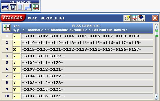 |
||||||||||||||||||||||||||||||
|
||||||||||||||||||||||||||||||
|
The program is interrupted when you analyze it as a one-story to try on an 8-story building information? If you have defined the building level as 8 and there are no elements in some floors, the program can be interrupted. Analyze how many floors have been created by giving the number of floors as much. Check data in case of error. Check floor coordinates in floor information. |
||||||||||||||||||||||||||||||
|
The program is interrupted after analysis, while editing the reinforcement? In some sections, too much reinforcement may be required due to excessive static loading. If the selected reinforcement diameters are also small, the program will be cut because the reinforcement will not fit into the section. Enter the reinforcement selection section and open the largest diameter bars. |
||||||||||||||||||||||||||||||
|
What versions of the STA4-CAD Windows operating system work with? STA4-CAD can work with Xp and VISTA version of Windows operating system. Since the Windows 2000 operating system uses the same kernel as XP, it is also compatible with Windows 2000, however, you should try it on your computer with the program's demo. Previous operating systems are not supported after V12. |
||||||||||||||||||||||||||||||
|
When using the STA4-CAD program, I get the message "no hasp" from time to time. What is the reason? Check if your lock is fully connected, if it is still check the parallel port it is connected to. Do not plug or unplug any hardware, including the lock, while your computer is open, you could damage your computer or hardware. |
||||||||||||||||||||||||||||||
|
In finite beams, in what case is the same name given? If beams are given the same name or different names, static calculations do not change in finite elements. Giving the same name will only affect reinforced concrete control and drawings. If negative support moment occurs at joint support moments of finite beams of the same name, which are divided side by side into finite beams, these beams operate as two separate beams. Therefore, additional reinforcement should be placed at the upper point of this joint. Although this was the case for K101 and K102 beams, it operated like a single beam in the K105 beam. Especially for the correct use of the batteries, it can be decided by looking at the dead load moment diagram. 
|
||||||||||||||||||||||||||||||
|
When should I do the fundamental analysis with the FEA part? If the stiffness of the plates is too important to be neglected (slab thickness is more than 1/3 of the basic beam thickness), analysis with the FEA part is required. 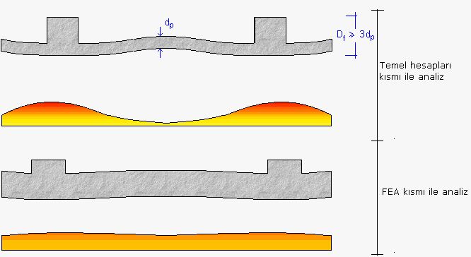 |
||||||||||||||||||||||||||||||
|
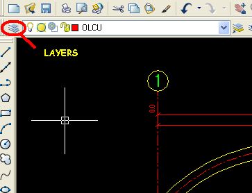
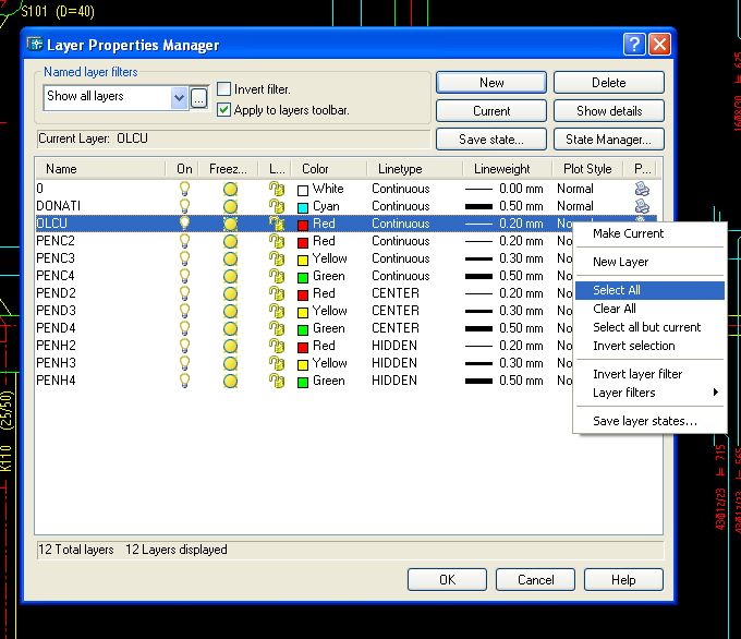
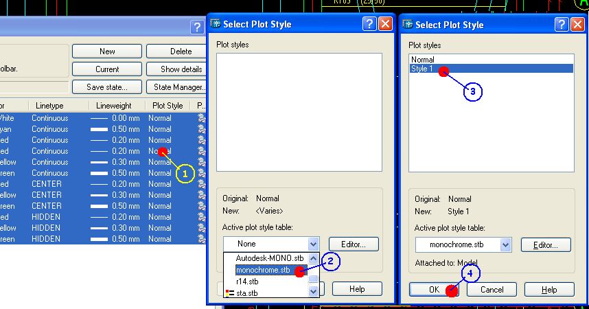
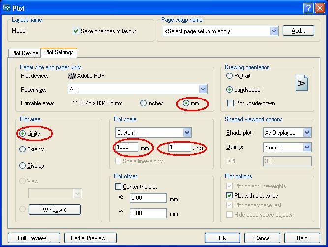
Black and white printout and scale in AutoCAD program printouts: In order to get black and white printouts in AutoCAD, the following method is followed:
|
||||||||||||||||||||||||||||||
|
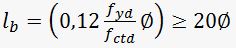
How is the shoot size in the columns calculated? The following points should be taken into consideration when calculating the column shoot lengths:
We can sample these rules as follows: Example 1: f16, C20, S420 for column element: fctd » 10.4 lb = 0.12 ´ (3652 / 10.4) ´ 1.6 » 67cm (In beams it is additionally multiplied by 1.4) 40 ´ f = 64cm < 67cm, lb = 67cm is calculated. In addition, the clamping length due to the earthquake regulation: 1.5 ´ 67cm = It is found as 101 cm. Örnek 2: f14, C20, S220, for beam element: lb = 0.12 ´ (1913 / 10.4) ´ 1.4´ 1.4 ´ 2 » It is found as 87 cm. |